Find the coordinates of the camera in Jmol
08 septembre 2011 | Catégories: jmol, sage | View CommentsIn Sage, we can create 3d graphic objects like the following:
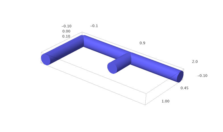
sage: a = line3d([(0,1,0), (0,0,0), (1,0,0), (2,0,0)], radius=0.1)
sage: b = line3d([(1,0,0), (1,0.5,0)], radius=0.1)
sage: g = a + b

sage: x,y = map(vector, g.bounding_box())
sage: g.frame_aspect_ratio(tuple(y-x))      # this sets the aspect ratio to 1

sage: g
Rotate the graphic object until you get a view you like.
One can save an image as a jpg, but the quality is not always good and one could prefer to draw the image using another tool like tikz code. But how to draw the 3d graphic object with the same projection?
To get information about the actual view and hopefully about the camera position, right clic on the image and go to the current state ("État courant" in French).
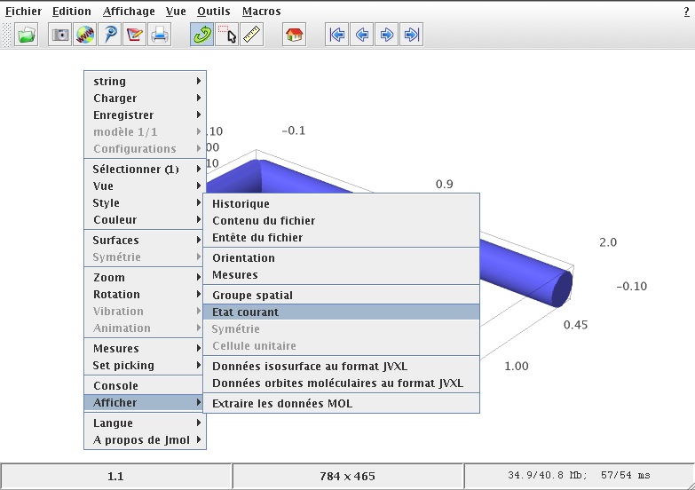
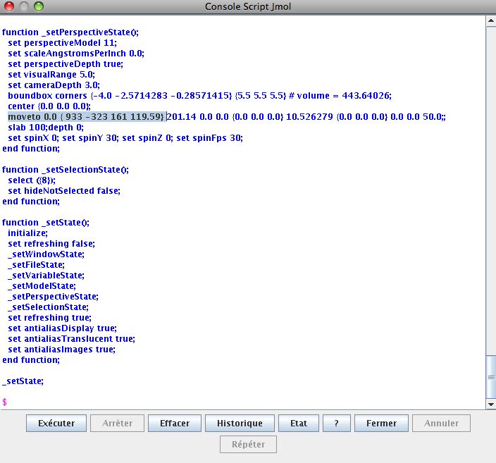
In the window that pops up, the information you need is the line starting with:
moveto 0.0 {933 -323 161 119.59}
According to the Jmol documentation of the moveto method (and also after doing some moveto tests in the script window), I understand that this tells that a rotation of angle \(119.59\) degrees is done on the axis \((933, -323, 161)\). The rotation is done counterclockwise (right-hand rule). From this information, we may then compute the rotation matrix using rotate_arbitrary method written by Robert Bradshaw and available in Sage. Note that the rotation of the method rotate_arbitrary is done counterclockwise (left-hand rule).
sage: from sage.plot.plot3d.transform import rotate_arbitrary
sage: v = (933, -323, 161)
sage: angle = 119.59                    # righ-hand rule
sage: angle = - angle                   # left-hand rule
sage: angle_rad = angle * pi / 180
sage: M = rotate_arbitrary(v, angle_rad)
sage: M
[  0.805577517225  -0.589785522899 -0.0565499842683]
[  -0.30988380511  -0.338059560724  -0.888643776062]
[  0.504991971294   0.733395371121  -0.455098163637]
Since the default position of the camera is on the positive Z axis, one can find the actual position of the camera by doing the inverse of the rotation on the vector \((0,0,1)\):
sage: camera = ~M * vector((0,0,1))
sage: camera
(0.504991971294, 0.733395371121, -0.455098163637)
To draw the same plot with the same angle of view in tikz, one needs the proper projection matrix:
sage: projection = M[:2]
sage: projection
[  0.805577517225  -0.589785522899 -0.0565499842683]
[  -0.30988380511  -0.338059560724  -0.888643776062]
One may test that this projection is really parallel to the segment that joins the origin to the camera:
sage: projection * camera
(5.55111512313e-17, 0.0)
The part of tikz code that gives the projection information is:
sage: s = '['
sage: s += 'x={(%scm, %scm)},\n' % tuple(projection * vector((1,0,0)))
sage: s += 'y={(%scm, %scm)},\n' % tuple(projection * vector((0,1,0)))
sage: s += 'z={(%scm, %scm)}'    % tuple(projection * vector((0,0,1)))
sage: s += ']'
sage: print s
[x={(0.805577517225cm, -0.30988380511cm)},
y={(-0.589785522899cm, -0.338059560724cm)},
z={(-0.0565499842683cm, -0.888643776062cm)}]
The complete tikz code is:
\begin{tikzpicture}
[x={(0.805577517225cm, -0.30988380511cm)},
y={(-0.589785522899cm, -0.338059560724cm)},
z={(-0.0565499842683cm, -0.888643776062cm)}, scale=3]
\draw[blue,line width=.4cm] (0,1,0) -- (0,0,0) -- (1,0,0) -- (2,0,0);
\draw[blue,line width=.4cm] (1,0,0) -- (1,0.5,0);
\end{tikzpicture}
The generated tikz image (pdf converted to a png: sorry for the bad quality) is:

One can verified that it has the same view as the original Jmol view.
Thanks to my brother Jean-Philippe who tested this method.
Propulsé par Blogofile
S'abonner au Flux RSS
et aux Commentaires.

This work by Sébastien Labbé is licensed under a Creative Commons Attribution-ShareAlike 4.0 International License.